Plasma Emission Monitor
Patent Title: Plasma Emission Monitor
Patent Certificate No.: I861840
This patented technology provides a novel plasma monitoring mechanism that ensures precise gas control and plasma uniformity in multi-target sputtering systems. It improves deposition stability and process repeatability, especially in high-end thin film applications.
[1] Patent Claims
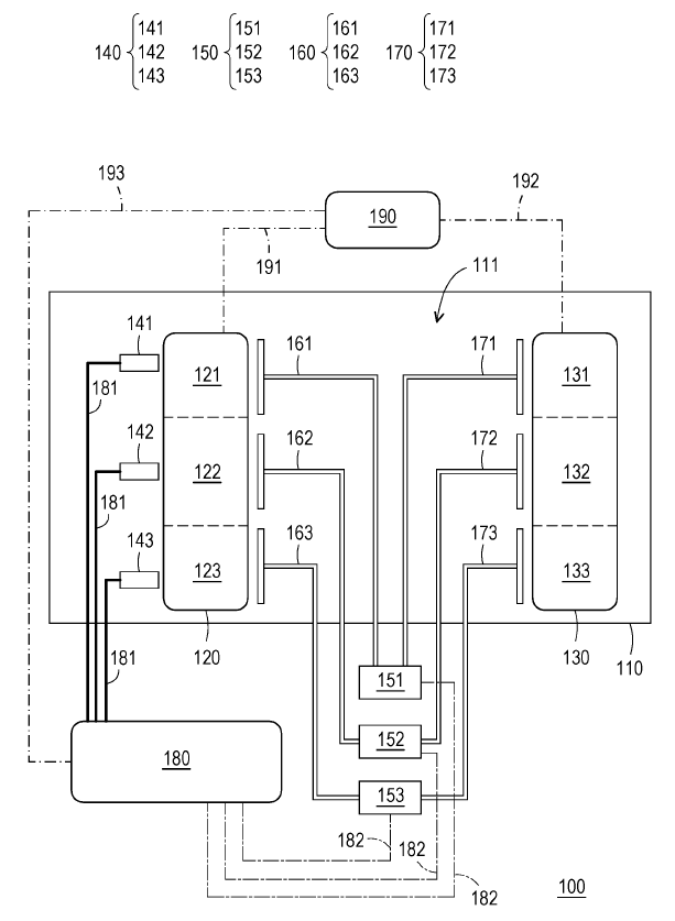
- A plasma emission monitor comprising: at least one first target holder with a first target that generates a first plasma; at least one second target holder with a second target that generates a second plasma; a first collimating lens assembly corresponding to the first target holder for detecting the first plasma spectrum. A first flow controller assembly provides gas to the first and second target holders via a first and second gas supply pipe set respectively. A plasma emission monitor adjusts the gas flow rate supplied by the first flow controller assembly based on the first plasma spectrum. The first and second targets are the same. The total number of collimating lens assemblies is less than the total number of target holders. Each of the first and second target holders corresponds to an independently arranged gas supply pipe set. The total number of gas supply pipe sets is equal to the total number of target holders and is greater than the number of collimating lens assemblies and flow controller assemblies.
- The plasma emission monitor of claim 1, wherein the number of collimating lens assemblies is one, and the number of target holders is two or more.
- The plasma emission monitor of claim 1, wherein the number of flow controller assemblies is less than the number of target holders.
- The plasma emission monitor of claim 3, wherein the number of flow controller assemblies is one, and the number of target holders is two or more.
- The plasma emission monitor of claim 1, wherein the first plasma light intensity of the first target holder is substantially equal to the second plasma light intensity of the second target holder.
- The plasma emission monitor of claim 1, wherein the difference in plasma light intensity between the first and second target holders is within 10%.
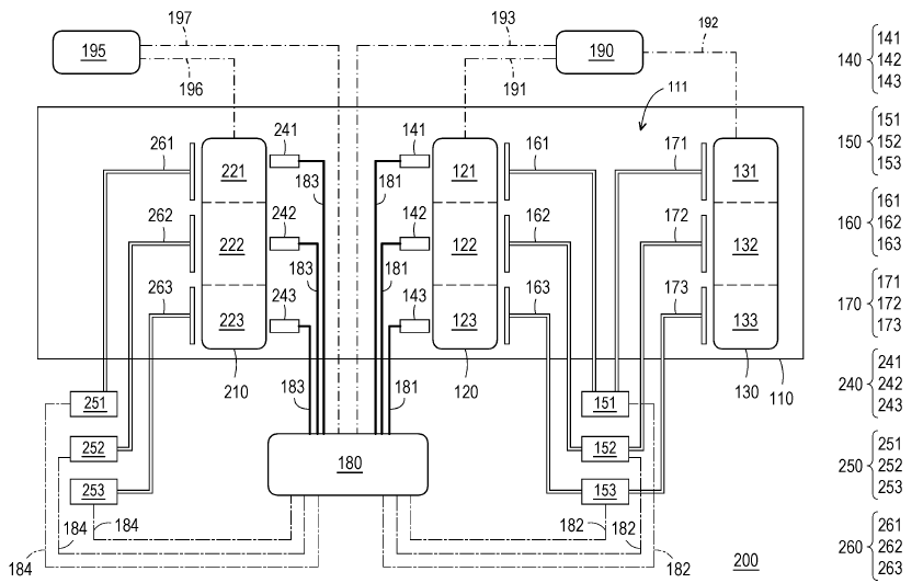
- The plasma emission monitor of claim 1, further comprising: at least one third target holder with a third target that generates a third plasma; a second collimating lens assembly corresponding to the third target holder to detect the third plasma intensity; and a second flow controller assembly that provides another gas to the third target holder via a third gas supply pipe set. The first and third targets are different, and the total number of collimating lens assemblies is less than the number of target holders.
- The plasma emission monitor of claim 7, wherein the number of collimating lens assemblies is two, and the number of target holders is three or more.
- The plasma emission monitor of claim 7, wherein the number of flow controller assemblies is less than the number of target holders.
- The plasma emission monitor of claim 9, wherein the number of flow controller assemblies is two, and the number of target holders is three or more.
[2] Figure Descriptions
- Figure 1: Schematic structure of the plasma emission monitor in one embodiment of the present invention.
- Figure 2: Schematic structure of the plasma emission monitor in another embodiment of the present invention.
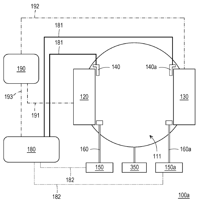
- Figure 3A: Schematic structure of the control group's plasma emission monitor.
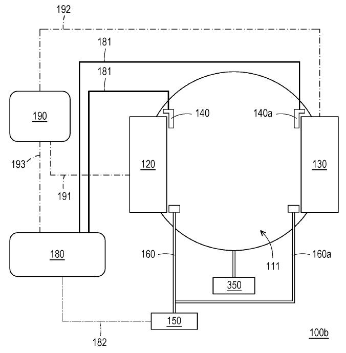
- Figure 3B: Schematic structure of the experimental group's plasma emission monitor.
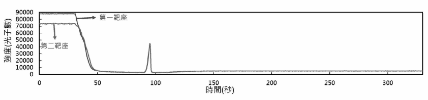
- Figure 4: Plasma spectra of two target holders in the control group with plasma light intensity preset at 5000 photons.
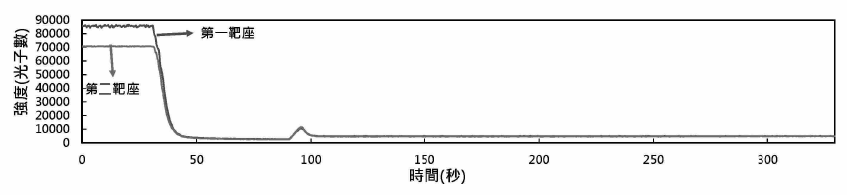
- Figure 5: Plasma spectra of two target holders in the experimental group with plasma light intensity preset at 5000 photons.
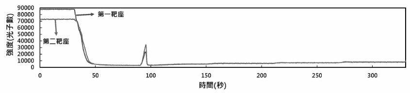
- Figure 6: Plasma spectra of two target holders in the control group with multiple preset photon levels.
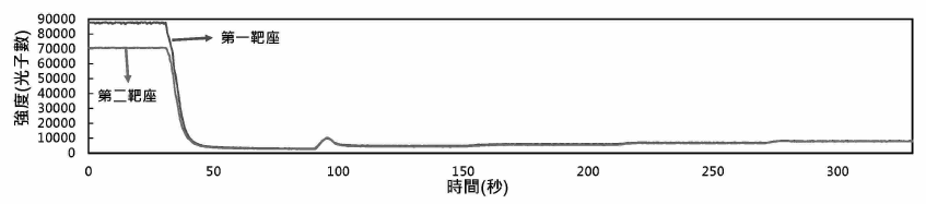
- Figure 7: Plasma spectra of two target holders in the experimental group with multiple preset photon levels.
【Figure 1】
【Figure 2】
【Figure 3】
【Figure 4】
【Figure 5】
【Figure 6】
【Figure 7】
【Figure 8】