Yarn Coating Chamber
Patent Certificate Number: I682047
Title:Yarn Coating Chamber
[1] Patent Claims
- A chamber having an opening, allowing an external vacuum device to connect to the interior of the chamber through said opening. The interior of the chamber comprises: a yarn guiding component, a yarn feeding roller, a chilled water roller, and a yarn winding roller; the chilled water roller is positioned between the yarn feeding roller and the yarn winding roller; the yarn guiding component is located on one side of the chilled water roller, and comprises multiple guiding sections, each of which is an annular recess, with spacing elements interposed between any two guiding sections; wherein the end of the yarn from the yarn feeding roller is first wound around the chilled water roller and the multiple guiding sections of the yarn guiding component before being wound onto the yarn winding roller.
- The chamber according to claim 1, wherein the multiple guiding sections are all limiting recesses, and any two guiding sections are connected by a toothed segment.
- The chamber according to claim 2, further comprising a tension roller, wherein the end of the yarn from the yarn feeding roller is first wound around the tension roller, and then collectively around the chilled water roller and the multiple guiding sections of the yarn guiding component, before being wound onto the yarn winding roller.
- The chamber according to claim 3, further comprising a tension roller, wherein the end of the yarn from the yarn feeding roller is first wound around the tension roller, and then collectively around the chilled water roller and the multiple guiding sections of the yarn guiding component, before being wound onto the yarn winding roller.
- A chamber having an opening, allowing an external vacuum device to connect to the interior of the chamber through said opening. The interior of the chamber comprises: a yarn guiding component, a yarn feeding roller, a chilled water roller, and a yarn winding roller; the chilled water roller is positioned between the yarn feeding roller and the yarn winding roller; the yarn guiding component is located on one side of the chilled water roller, and comprises multiple guiding sections, which are all annular rotating elements pivotally mounted on the yarn guiding component, with spacing elements interposed between any two guiding sections; wherein the end of the yarn from the yarn feeding roller is first wound around the chilled water roller and the multiple guiding sections of the yarn guiding component before being wound onto the yarn winding roller.
- The chamber according to claim 5, further comprising a tension roller, wherein the end of the yarn from the yarn feeding roller is first wound around the tension roller, and then collectively around the chilled water roller and the multiple guiding sections of the yarn guiding component, before being wound onto the yarn winding roller.
- The chamber according to any of claims 1 to 6, further comprising a yarn aligning roller disposed near the yarn feeding roller or the yarn winding roller.
- The chamber according to claim 7, wherein the chamber has another opening allowing an external coating source to communicate with the chamber through the opening, and is positioned opposite the other side of the chilled water roller.
- The chamber according to any of claims 1 to 6, wherein the chamber has another opening allowing an external coating source to communicate with the chamber through the opening, and is positioned opposite the other side of the chilled water roller.
- Figure 1 is a perspective view of the first preferred embodiment of the present invention.
- Figure 2 is a perspective view of a partial component of the chamber shown in Figure 1.
- Figure 3 is a perspective view of another partial component of the chamber shown in Figure 1.
- Figure 4 is a front view of the component shown in Figure 3.
- Figure 5 is a top view illustrating the application of the first preferred embodiment of the present invention.
- Figure 6 is a perspective view illustrating the application of the first preferred embodiment of the present invention.
- Figure 7 is a perspective view of another yarn guiding component in the second preferred embodiment of the present invention.
-
Figure 8 is a perspective view of yet another yarn guiding component in the third preferred embodiment of the present invention.
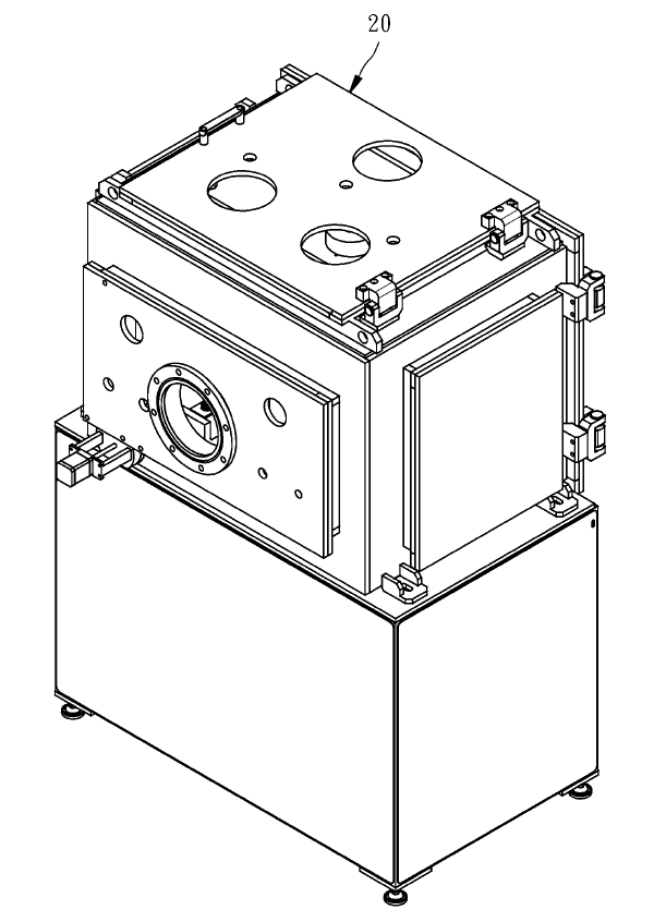
[Figure 1]
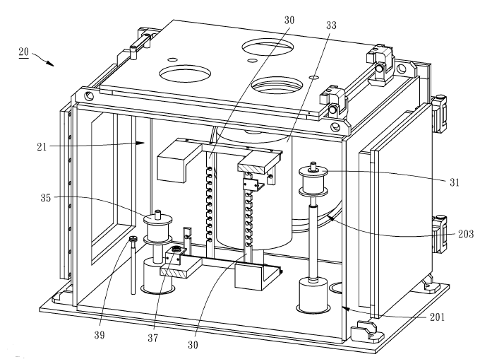
[Figure 2]
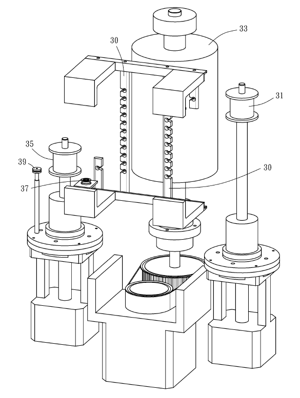
[Figure 3]
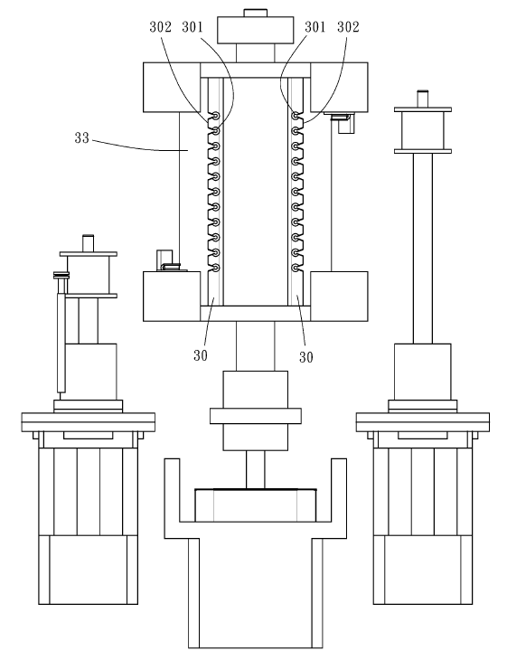
[Figure 4]
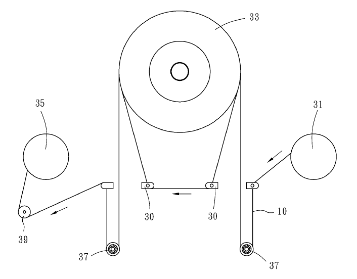
[Figure 5]
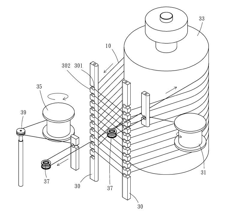
[Figure 6]
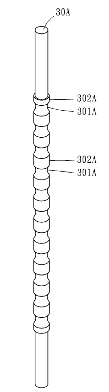
[Figure 7]
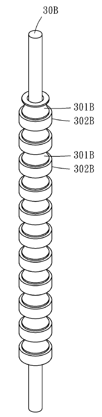
[Figure 8]